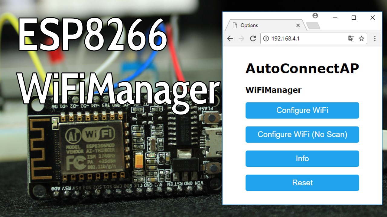
WiFiManager с ESP8266 — автоподключение, пользовательские параметры и управление SSID и паролем
В этом руководстве вы узнаете, как использовать WiFiManager с платой ESP8266. WiFiManager позволяет подключать ESP8266 к различным точкам доступа (AP) без необходимости жёстко прописывать и загружать новый код на плату. Кроме того, вы также можете добавлять пользовательские параметры (переменные) и управлять несколькими SSID-подключениями с помощью библиотеки WiFiManager.
Как WiFiManager работает с ESP8266
WiFiManager — отличная библиотека для добавления в ваши проекты на ESP8266, потому что при использовании этой библиотеки вам больше не нужно жёстко прописывать сетевые учётные данные (SSID и пароль). Ваш ESP автоматически подключится к известной сети или настроит точку доступа, которую вы можете использовать для конфигурации сетевых учётных данных. Вот как работает этот процесс:
Когда ESP8266 загружается, он настраивается в режиме станции (Station mode) и пытается подключиться к ранее сохранённой точке доступа (известная комбинация SSID и пароля);
Если этот процесс завершается неудачей, ESP переводится в режим точки доступа (Access Point mode);
Используя любое устройство с поддержкой Wi-Fi и браузером, подключитесь к вновь созданной точке доступа (имя по умолчанию AutoConnectAP);
После установления соединения с AutoConnectAP вы можете перейти по IP-адресу по умолчанию 192.168.4.1, чтобы открыть веб-страницу, которая позволяет настроить SSID и пароль;
После установки нового SSID и пароля ESP перезагружается и пытается подключиться;
Если соединение установлено, процесс завершается успешно. В противном случае ESP снова будет настроен как точка доступа.
Эта статья иллюстрирует два различных варианта использования библиотеки WiFiManager:
Пример #1 — Автоподключение: пример веб-сервера
Пример #2 — Добавление пользовательских параметров
Необходимые условия
Перед тем как приступить к этому руководству, рекомендуем ознакомиться со следующими ресурсами:
Установка WiFiManager и ArduinoJSON
Вам также необходимо установить библиотеку WiFiManager и библиотеку ArduinoJSON. Следуйте приведённым ниже инструкциям.
Установка библиотеки WiFiManager
Нажмите здесь, чтобы скачать библиотеку WiFiManager. У вас должна появиться .zip-папка в разделе «Загрузки»
Распакуйте .zip-папку, и вы должны получить папку WiFiManager-master
Переименуйте папку из WiFiManager-master в WiFiManager
Переместите папку WiFiManager в папку libraries вашей установки Arduino IDE
Наконец, перезапустите Arduino IDE
Установка библиотеки ArduinoJSON
Нажмите здесь, чтобы скачать библиотеку ArduinoJSON. У вас должна появиться .zip-папка в разделе «Загрузки»
Распакуйте .zip-папку, и вы должны получить папку ArduinoJSON-master
Переименуйте папку из ArduinoJSON-master в ArduinoJSON
Переместите папку ArduinoJSON в папку libraries вашей установки Arduino IDE
Наконец, перезапустите Arduino IDE
Узнайте больше о том, как декодировать и кодировать JSON с Arduino или ESP8266, используя библиотеку Arduino JSON.
Пример #1 — WiFiManager с ESP8266: пример автоподключения
Этот первый пример основан на статье о веб-сервере ESP8266, в которой вы создаёте веб-сервер с ESP8266 для управления двумя выходами (смотрите видео-урок ниже).
Для Примера #1 мы будем использовать предыдущий проект, но вместо жёсткого прописывания SSID и пароля вы сможете настроить их с помощью библиотеки WiFiManager.
Код
Установив дополнение ESP8266 для Arduino IDE (Как установить плату ESP8266 в Arduino IDE), перейдите в Tools и выберите «ESP-12E» (или выберите используемую вами плату разработки). Вот код, который вам нужно загрузить на ESP8266:
/*********
  Rui Santos
  Complete project details at https://randomnerdtutorials.com
*********/

#include <ESP8266WiFi.h>
#include <DNSServer.h>
#include <ESP8266WebServer.h>
#include <WiFiManager.h>         // https://github.com/tzapu/WiFiManager

// Set web server port number to 80
WiFiServer server(80);

// Variable to store the HTTP request
String header;

// Auxiliar variables to store the current output state
String output5State = "off";
String output4State = "off";

// Assign output variables to GPIO pins
const int output5 = 5;
const int output4 = 4;

void setup() {
  Serial.begin(115200);

  // Initialize the output variables as outputs
  pinMode(output5, OUTPUT);
  pinMode(output4, OUTPUT);
  // Set outputs to LOW
  digitalWrite(output5, LOW);
  digitalWrite(output4, LOW);

  // WiFiManager
  // Local intialization. Once its business is done, there is no need to keep it around
  WiFiManager wifiManager;

  // Uncomment and run it once, if you want to erase all the stored information
  //wifiManager.resetSettings();

  // set custom ip for portal
  //wifiManager.setAPConfig(IPAddress(10,0,1,1), IPAddress(10,0,1,1), IPAddress(255,255,255,0));

  // fetches ssid and pass from eeprom and tries to connect
  // if it does not connect it starts an access point with the specified name
  // here  "AutoConnectAP"
  // and goes into a blocking loop awaiting configuration
  wifiManager.autoConnect("AutoConnectAP");
  // or use this for auto generated name ESP + ChipID
  //wifiManager.autoConnect();

  // if you get here you have connected to the WiFi
  Serial.println("Connected.");

  server.begin();
}

void loop(){
  WiFiClient client = server.available();   // Listen for incoming clients

  if (client) {                             // If a new client connects,
    Serial.println("New Client.");          // print a message out in the serial port
    String currentLine = "";                // make a String to hold incoming data from the client
    while (client.connected()) {            // loop while the client's connected
      if (client.available()) {             // if there's bytes to read from the client,
        char c = client.read();             // read a byte, then
        Serial.write(c);                    // print it out the serial monitor
        header += c;
        if (c == '\n') {                    // if the byte is a newline character
          // if the current line is blank, you got two newline characters in a row.
          // that's the end of the client HTTP request, so send a response:
          if (currentLine.length() == 0) {
            // HTTP headers always start with a response code (e.g. HTTP/1.1 200 OK)
            // and a content-type so the client knows what's coming, then a blank line:
            client.println("HTTP/1.1 200 OK");
            client.println("Content-type:text/html");
            client.println("Connection: close");
            client.println();

            // turns the GPIOs on and off
            if (header.indexOf("GET /5/on") >= 0) {
              Serial.println("GPIO 5 on");
              output5State = "on";
              digitalWrite(output5, HIGH);
            } else if (header.indexOf("GET /5/off") >= 0) {
              Serial.println("GPIO 5 off");
              output5State = "off";
              digitalWrite(output5, LOW);
            } else if (header.indexOf("GET /4/on") >= 0) {
              Serial.println("GPIO 4 on");
              output4State = "on";
              digitalWrite(output4, HIGH);
            } else if (header.indexOf("GET /4/off") >= 0) {
              Serial.println("GPIO 4 off");
              output4State = "off";
              digitalWrite(output4, LOW);
            }

            // Display the HTML web page
            client.println("<!DOCTYPE html><html>");
            client.println("<head><meta name=\"viewport\" content=\"width=device-width, initial-scale=1\">");
            client.println("<link rel=\"icon\" href=\"data:,\">");
            // CSS to style the on/off buttons
            // Feel free to change the background-color and font-size attributes to fit your preferences
            client.println("<style>html { font-family: Helvetica; display: inline-block; margin: 0px auto; text-align: center;}");
            client.println(".button { background-color: #195B6A; border: none; color: white; padding: 16px 40px;");
            client.println("text-decoration: none; font-size: 30px; margin: 2px; cursor: pointer;}");
            client.println(".button2 {background-color: #77878A;}</style></head>");

            // Web Page Heading
            client.println("<body><h1>ESP8266 Web Server</h1>");

            // Display current state, and ON/OFF buttons for GPIO 5
            client.println("<p>GPIO 5 - State " + output5State + "</p>");
            // If the output5State is off, it displays the ON button
            if (output5State=="off") {
              client.println("<p><a href=\"/5/on\"><button class=\"button\">ON</button></a></p>");
            } else {
              client.println("<p><a href=\"/5/off\"><button class=\"button button2\">OFF</button></a></p>");
            }

            // Display current state, and ON/OFF buttons for GPIO 4
            client.println("<p>GPIO 4 - State " + output4State + "</p>");
            // If the output4State is off, it displays the ON button
            if (output4State=="off") {
              client.println("<p><a href=\"/4/on\"><button class=\"button\">ON</button></a></p>");
            } else {
              client.println("<p><a href=\"/4/off\"><button class=\"button button2\">OFF</button></a></p>");
            }
            client.println("</body></html>");

            // The HTTP response ends with another blank line
            client.println();
            // Break out of the while loop
            break;
          } else { // if you got a newline, then clear currentLine
            currentLine = "";
          }
        } else if (c != '\r') {  // if you got anything else but a carriage return character,
          currentLine += c;      // add it to the end of the currentLine
        }
      }
    }
    // Clear the header variable
    header = "";
    // Close the connection
    client.stop();
    Serial.println("Client disconnected.");
    Serial.println("");
  }
}
Этот код должен подключать следующие библиотеки для WiFiManager:
#include <DNSServer.h>
#include <ESP8266WebServer.h>
#include <WiFiManager.h>
Вам также нужно создать объект WiFiManager:
WiFiManager wifiManager;
И запустить метод autoConnect():
wifiManager.autoConnect("AutoConnectAP");
Вот и всё! Добавив эти новые строки кода в ваши проекты на ESP8266, вы сможете настраивать учётные данные Wi-Fi с помощью WiFiManager.
Доступ к точке доступа WiFiManager
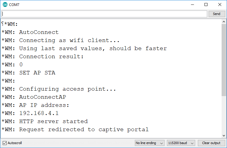
Если вы впервые запускаете код WiFiManager на плате ESP8266, вы увидите следующие сообщения в мониторе последовательного порта Arduino IDE.
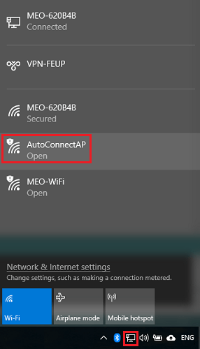
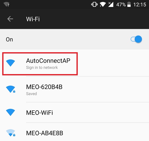
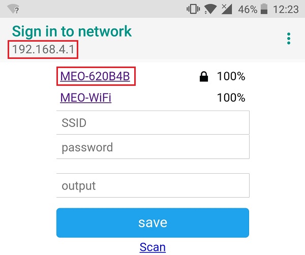
Вы можете использовать компьютер/ноутбук для подключения к точке доступа AutoConnectAP:
Затем откройте браузер и введите следующий IP-адрес: 192.168.4.1. Откроется следующая веб-страница, где вы можете настроить учётные данные Wi-Fi:

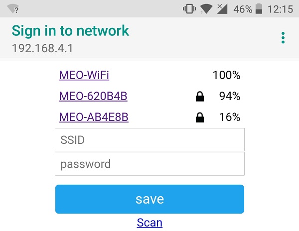
Кроме того, вы можете использовать смартфон, активировать Wi-Fi и подключиться к AutoConnectAP следующим образом:
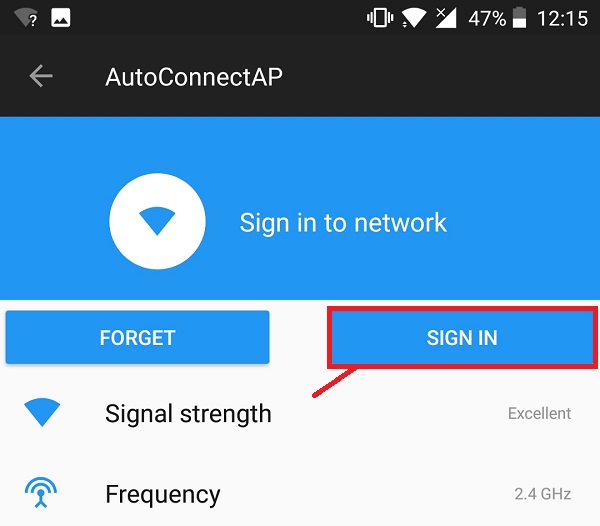
Вы должны увидеть окно, похожее на показанное на рисунке ниже. Затем нажмите кнопку «SIGN IN»:
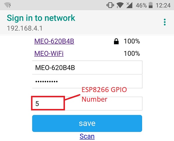
Настройка страницы WiFi
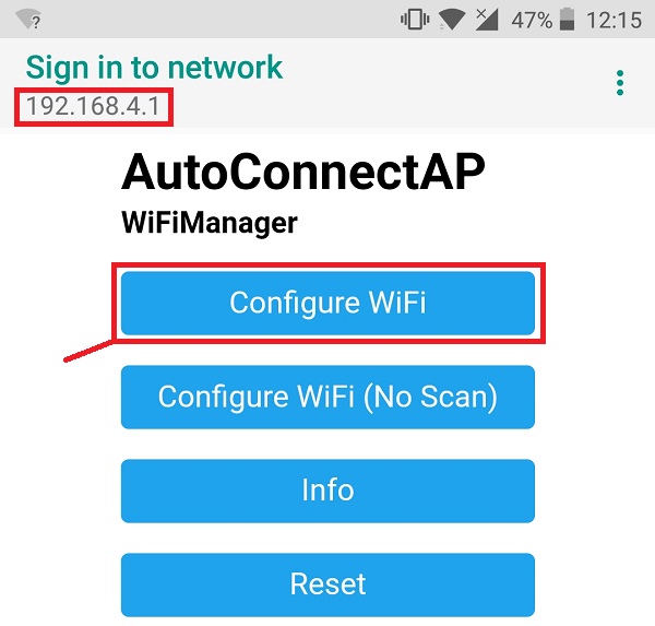
Вы будете перенаправлены на веб-страницу по адресу 192.168.4.1, которая позволяет настроить учётные данные WiFi вашего ESP. Нажмите кнопку «Configure WiFi»:
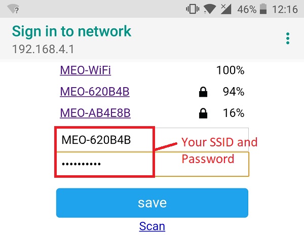
Выберите нужную сеть, нажав на её имя, и SSID должен заполниться автоматически (в моём случае «MEO-620B4B»):
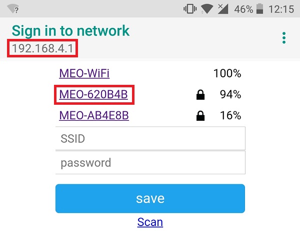
После этого введите пароль и нажмите «save»:
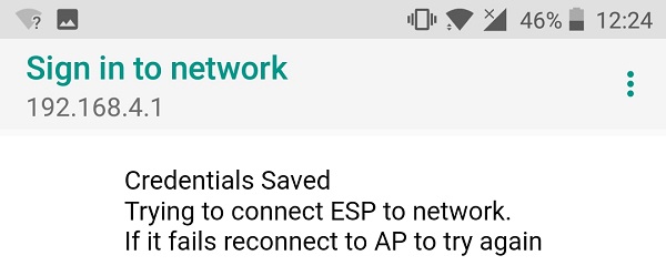
Вы увидите похожее сообщение «Credentials Saved»:
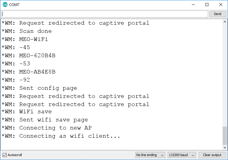
Тем временем монитор последовательного порта отображает результаты сканирования доступных точек доступа и сообщение о том, что учётные данные Wi-Fi были сохранены.
Доступ к веб-серверу
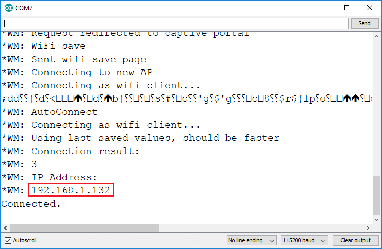
Теперь, если вы СБРОСИТЕ плату ESP, она выведет IP-адрес в мониторе последовательного порта (в моём случае это 192.168.1.132):
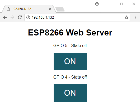
Откройте браузер и введите IP-адрес. Вы должны увидеть веб-сервер, показанный ниже, который позволяет включать и выключать два GPIO:
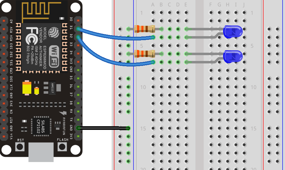
Необходимые компоненты и схема
Если вы хотите, чтобы этот проект работал, вот необходимые компоненты:
ESP8266 12-E — читайте Лучшие платы разработки ESP8266 Wi-Fi
2x резистора (220 или 330 Ом подойдут)
Вы можете использовать приведённые выше ссылки или перейти напрямую на MakerAdvisor.com/tools, чтобы найти все компоненты для ваших проектов по лучшей цене!
Следуйте этой схеме:
Как стереть учётные данные с ESP8266
Следующая строка по умолчанию закомментирована, иначе вам пришлось бы настраивать ESP8266 при каждой загрузке.
// Uncomment and run it once, if you want to erase all the stored information
//wifiManager.resetSettings();
Если по какой-то причине вы хотите стереть все сохранённые учётные данные:
Раскомментируйте указанную выше строку;
Загрузите код на ESP8266;
Дайте ему выполниться один раз (сбросьте плату);
Закомментируйте эту строку снова;
Загрузите код на ESP8266 с закомментированной строкой.
Пример #2 — WiFiManager с ESP8266 и пользовательскими параметрами
WiFiManager имеет полезную функцию, которая позволяет добавлять пользовательские параметры на веб-страницу «Configure WiFi». Это чрезвычайно полезно, потому что в некоторых приложениях вам может потребоваться добавить другой API-ключ, IP-адрес брокера MQTT, назначить другой GPIO, активировать датчик и т.д.
В Примере #2 вы создадите веб-сервер для управления GPIO-выводом ESP8266, который определяется пользовательским параметром, установленным через WiFiManager.
Код
Установив дополнение ESP8266 для Arduino IDE (Как установить плату ESP8266 в Arduino IDE), перейдите в Tools и выберите «ESP-12E» (или выберите используемую вами плату разработки). Вот код, который вам нужно загрузить на ESP8266:
/*********
  Rui Santos
  Complete project details at https://randomnerdtutorials.com
*********/

#include <FS.h> //this needs to be first, or it all crashes and burns...
#include <ESP8266WiFi.h>
#include <DNSServer.h>
#include <ESP8266WebServer.h>
#include <WiFiManager.h>          // https://github.com/tzapu/WiFiManager
#include <ArduinoJson.h>          // https://github.com/bblanchon/ArduinoJson

// Set web server port number to 80
WiFiServer server(80);

// Variable to store the HTTP request
String header;

// Auxiliar variables to store the current output state
String outputState = "off";

// Assign output variables to GPIO pins
char output[2] = "5";

//flag for saving data
bool shouldSaveConfig = false;

//callback notifying us of the need to save config
void saveConfigCallback () {
  Serial.println("Should save config");
  shouldSaveConfig = true;
}

void setup() {
  Serial.begin(115200);

  //clean FS, for testing
  //SPIFFS.format();

  //read configuration from FS json
  Serial.println("mounting FS...");

  if (SPIFFS.begin()) {
    Serial.println("mounted file system");
    if (SPIFFS.exists("/config.json")) {
      //file exists, reading and loading
      Serial.println("reading config file");
      File configFile = SPIFFS.open("/config.json", "r");
      if (configFile) {
        Serial.println("opened config file");
        size_t size = configFile.size();
        // Allocate a buffer to store contents of the file.
        std::unique_ptr<char[]> buf(new char[size]);

        configFile.readBytes(buf.get(), size);
        DynamicJsonBuffer jsonBuffer;
        JsonObject& json = jsonBuffer.parseObject(buf.get());
        json.printTo(Serial);
        if (json.success()) {
          Serial.println("\nparsed json");
          strcpy(output, json["output"]);
        } else {
          Serial.println("failed to load json config");
        }
      }
    }
  } else {
    Serial.println("failed to mount FS");
  }
  //end read

  WiFiManagerParameter custom_output("output", "output", output, 2);

  // WiFiManager
  // Local intialization. Once its business is done, there is no need to keep it around
  WiFiManager wifiManager;

  //set config save notify callback
  wifiManager.setSaveConfigCallback(saveConfigCallback);

  // set custom ip for portal
  //wifiManager.setAPConfig(IPAddress(10,0,1,1), IPAddress(10,0,1,1), IPAddress(255,255,255,0));

  //add all your parameters here
  wifiManager.addParameter(&custom_output);

  // Uncomment and run it once, if you want to erase all the stored information
  //wifiManager.resetSettings();

  //set minimu quality of signal so it ignores AP's under that quality
  //defaults to 8%
  //wifiManager.setMinimumSignalQuality();

  //sets timeout until configuration portal gets turned off
  //useful to make it all retry or go to sleep
  //in seconds
  //wifiManager.setTimeout(120);

  // fetches ssid and pass from eeprom and tries to connect
  // if it does not connect it starts an access point with the specified name
  // here  "AutoConnectAP"
  // and goes into a blocking loop awaiting configuration
  wifiManager.autoConnect("AutoConnectAP");
  // or use this for auto generated name ESP + ChipID
  //wifiManager.autoConnect();

  // if you get here you have connected to the WiFi
  Serial.println("Connected.");

  strcpy(output, custom_output.getValue());

  //save the custom parameters to FS
  if (shouldSaveConfig) {
    Serial.println("saving config");
    DynamicJsonBuffer jsonBuffer;
    JsonObject& json = jsonBuffer.createObject();
    json["output"] = output;

    File configFile = SPIFFS.open("/config.json", "w");
    if (!configFile) {
      Serial.println("failed to open config file for writing");
    }

    json.printTo(Serial);
    json.printTo(configFile);
    configFile.close();
    //end save
  }

  // Initialize the output variables as outputs
  pinMode(atoi(output), OUTPUT);
  // Set outputs to LOW
  digitalWrite(atoi(output), LOW);;

  server.begin();
}

void loop(){
  WiFiClient client = server.available();   // Listen for incoming clients

  if (client) {                             // If a new client connects,
    Serial.println("New Client.");          // print a message out in the serial port
    String currentLine = "";                // make a String to hold incoming data from the client
    while (client.connected()) {            // loop while the client's connected
      if (client.available()) {             // if there's bytes to read from the client,
        char c = client.read();             // read a byte, then
        Serial.write(c);                    // print it out the serial monitor
        header += c;
        if (c == '\n') {                    // if the byte is a newline character
          // if the current line is blank, you got two newline characters in a row.
          // that's the end of the client HTTP request, so send a response:
          if (currentLine.length() == 0) {
            // HTTP headers always start with a response code (e.g. HTTP/1.1 200 OK)
            // and a content-type so the client knows what's coming, then a blank line:
            client.println("HTTP/1.1 200 OK");
            client.println("Content-type:text/html");
            client.println("Connection: close");
            client.println();

            // turns the GPIOs on and off
            if (header.indexOf("GET /output/on") >= 0) {
              Serial.println("Output on");
              outputState = "on";
              digitalWrite(atoi(output), HIGH);
            } else if (header.indexOf("GET /output/off") >= 0) {
              Serial.println("Output off");
              outputState = "off";
              digitalWrite(atoi(output), LOW);
            }

            // Display the HTML web page
            client.println("<!DOCTYPE html><html>");
            client.println("<head><meta name=\"viewport\" content=\"width=device-width, initial-scale=1\">");
            client.println("<link rel=\"icon\" href=\"data:,\">");
            // CSS to style the on/off buttons
            // Feel free to change the background-color and font-size attributes to fit your preferences
            client.println("<style>html { font-family: Helvetica; display: inline-block; margin: 0px auto; text-align: center;}");
            client.println(".button { background-color: #195B6A; border: none; color: white; padding: 16px 40px;");
            client.println("text-decoration: none; font-size: 30px; margin: 2px; cursor: pointer;}");
            client.println(".button2 {background-color: #77878A;}</style></head>");

            // Web Page Heading
            client.println("<body><h1>ESP8266 Web Server</h1>");

            // Display current state, and ON/OFF buttons for the defined GPIO
            client.println("<p>Output - State " + outputState + "</p>");
            // If the outputState is off, it displays the ON button
            if (outputState=="off") {
              client.println("<p><a href=\"/output/on\"><button class=\"button\">ON</button></a></p>");
            } else {
              client.println("<p><a href=\"/output/off\"><button class=\"button button2\">OFF</button></a></p>");
            }
            client.println("</body></html>");

            // The HTTP response ends with another blank line
            client.println();
            // Break out of the while loop
            break;
          } else { // if you got a newline, then clear currentLine
            currentLine = "";
          }
        } else if (c != '\r') {  // if you got anything else but a carriage return character,
          currentLine += c;      // add it to the end of the currentLine
        }
      }
    }
    // Clear the header variable
    header = "";
    // Close the connection
    client.stop();
    Serial.println("Client disconnected.");
    Serial.println("");
  }
}
Добавление пользовательских параметров
Чтобы добавить пользовательский параметр, вам необходимо добавить фрагмент кода (см. предыдущий скетч), который позволяет манипулировать файлом /config.json, хранящимся в ESP. В этом руководстве мы не будем объяснять, как работает функция пользовательских параметров, но в целом, если вы хотите создать ещё один пользовательский параметр, выполните следующие шаги.
В этом примере мы создадим переменную для хранения IP-адреса брокера MQTT. Сначала создайте переменную типа char:
char output[2];
char mqtt_server[40];
Затем, если она уже сохранена в /config.json, вы можете скопировать её:
strcpy(output, json["output"]);
strcpy(mqtt_server, json["mqtt_server"]);
Создайте WiFiManagerParameter (чтобы параметр отображался на веб-странице «Configure WiFi»):
WiFiManagerParameter custom_output("output", "output", output, 2);
WiFiManagerParameter custom_mqtt_server("server", "mqtt server", mqtt_server, 40);
Добавьте переменную как параметр:
wifiManager.addParameter(&custom_output);
wifiManager.addParameter(&custom_mqtt_server);
Проверьте и обновите переменные char последним значением:
strcpy(output, custom_output.getValue());
strcpy(mqtt_server, custom_mqtt_server.getValue());
Наконец, если пользователь отправит новое значение одного из параметров, эта строка обновит файл /config.json:
json["output"] = output;
json["mqtt_server"] = mqtt_server;
Вы можете повторить этот процесс для добавления большего количества пользовательских параметров.
Доступ к точке доступа WiFiManager
Используйте смартфон, компьютер или планшет и подключитесь к точке доступа AutoConnectAP:
Вы должны увидеть окно, похожее на показанное на рисунке ниже. Затем нажмите кнопку «SIGN IN»:
Настройка страницы WiFi
Вы будете перенаправлены на веб-страницу по адресу 192.168.4.1, которая позволяет настроить учётные данные WiFi вашего ESP. Нажмите кнопку «Configure WiFi»:
Выберите нужную сеть, нажав на её имя, и SSID должен заполниться автоматически (в моём случае «MEO-620B4B»):
После этого введите пароль, желаемый номер GPIO (в моём случае это GPIO 5, поэтому я ввёл 5) и нажмите «save»:
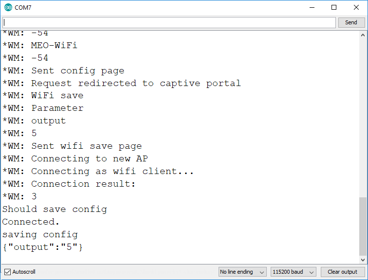
Тем временем монитор последовательного порта отображает:
Результаты сканирования доступных точек доступа;
Сообщение о том, что учётные данные Wi-Fi были сохранены;
Подтверждение того, что параметр output (который относится к GPIO) был установлен на 5: {«output»:»5»}.
Доступ к веб-серверу
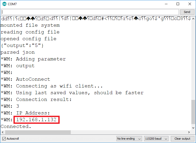
Теперь, если вы СБРОСИТЕ плату ESP, она выведет IP-адрес в мониторе последовательного порта (в моём случае это 192.168.1.132):
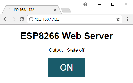
Откройте браузер и введите IP-адрес. Вы должны увидеть веб-сервер, показанный ниже, который позволяет включать и выключать GPIO, определённый вами:
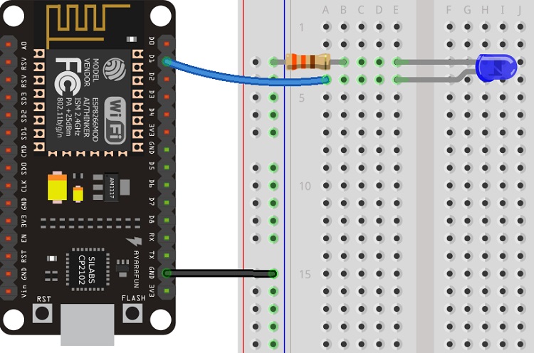
Необходимые компоненты и схема
Если вы хотите, чтобы этот проект работал, вот необходимые компоненты:
ESP8266 12-E — читайте Лучшие платы разработки ESP8266 Wi-Fi
1x резистор (220 или 330 Ом подойдут)
Вы можете использовать приведённые выше ссылки или перейти напрямую на MakerAdvisor.com/tools, чтобы найти все компоненты для ваших проектов по лучшей цене!
Примечание: если вы определили номер GPIO, отличный от GPIO 5 (который соответствует D1 на плате NodeMCU), вам нужно собрать другую схему.
Заключение
На этом всё, надеемся, что вы нашли этот проект полезным и сможете использовать библиотеку WiFiManager в своих проектах!
Если вам нравится ESP8266, вам также могут понравиться: