Arduino к Arduino через Bluetooth
Обновлено 12.06.2016: Добавлен пример 2
В статье Подключение 2 Arduino через Bluetooth с помощью HC-05 и HC-06: Pair, Bind и Link автор объяснил, как подключить HC-05 к HC-06 так, чтобы при включении они автоматически устанавливали соединение. Здесь мы рассмотрим использование этого соединения для организации связи между Arduino через Bluetooth. Перед продолжением необходимо настроить Arduino и BT-модули согласно предыдущей статье. В данном примере используются 2 модуля HC-05: один в режиме Master, другой в режиме Slave. Процесс настройки HC-05 в режиме Slave аналогичен настройке HC-06 из предыдущей статьи.
Настройка
Используются 5В Arduino Nano, но подойдёт любой 5В AVR-Arduino.
Одна из Arduino обозначена как ведущее устройство (Master). Это устройство, которое инициирует соединение, и в первом примере именно оно отправляет команды. Схема Master-Slave немного упрощает программирование.
Для связи с BT-модулями используется библиотека AltSoftSerial, которая задействует пины 8 и 9. Библиотеку AltSoftSerial можно скачать с https://www.pjrc.com/teensy/td_libs_AltSoftSerial.html — её необходимо установить перед компиляцией примеров.
Оба BT-модуля настроены на скорость 9600 бод. Её можно изменить, но убедитесь, что скорость совпадает с указанной при открытии программного последовательного соединения.
//  open software serial connection to the Bluetooth module.
BTserial.begin(9600);
Подключение Bluetooth-модулей
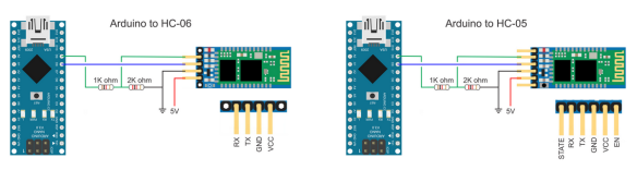
Большинство HC-05 и HC-06 имеют пины TX и RX на 3.3В. 5В Arduino считает 3.3В как HIGH, поэтому пин TX BT-модуля можно подключить напрямую к пину RX Arduino. Однако пин TX Arduino необходимо преобразовать в 3.3В перед подключением к пину RX BT-модуля. Простой способ — использовать делитель напряжения из 2 резисторов; обычно используется 1 x 1 кОм и 1 x 2 кОм.
Arduino RX (пин 8) к пину TX BT-модуля
Arduino TX (пин 9) к пину RX BT-модуля через делитель напряжения
Оба Arduino имеют одинаковые подключения к BT-модулям.
Пример 1: Удалённое управление светодиодом
В первом примере одна Arduino управляет светодиодом, подключённым ко второй Arduino. Связь односторонняя, без проверки ошибок. Arduino #1 просто отправляет команды LEDON и LEDOFF на Arduino #2. Когда Arduino #2 получает команды, она устанавливает светодиод соответственно.
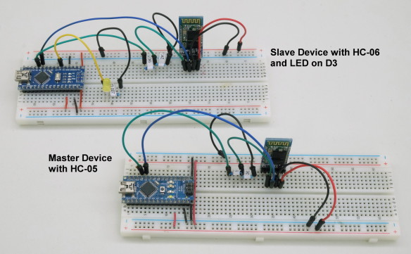
Пример 1: Схема
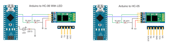
Arduino #1 (ведущее устройство) имеет только Bluetooth-модуль. Arduino #2 (ведомое устройство) имеет Bluetooth-модуль и светодиод (с подходящим резистором) на пине D3.

Пример 1: Скетчи
Скетч на Arduino #1 (ведущее устройство, подключённое к HC-05) просто отправляет команду LEDON, ждёт секунду, отправляет команду LEDOFF, ждёт ещё секунду и повторяет бесконечно.
/*
* Sketch: Arduino2Arduino_MASTER_01
* By Martyn Currey
* 08.04.2016
* Written in Arduino IDE 1.6.3
*
* Send commands through a serial connection to turn a LED on and OFF on a remote Arduino
* There is no error checking and this sketch sends only
* Commands should be contained within the start and end markers < and >
*
* D8 - AltSoftSerial RX
* D9 - AltSoftSerial TX
*
*/

// AltSoftSerial uses D9 for TX and D8 for RX. While using AltSoftSerial D10 cannot be used for PWM.
// Remember to use a voltage divider on the Arduino TX pin / Bluetooth RX pin
// Download AltSoftSerial from https://www.pjrc.com/teensy/td_libs_AltSoftSerial.html

#include <AltSoftSerial.h>
AltSoftSerial BTserial;

// Change DEBUG to true to output debug information to the serial monitor
boolean DEBUG = true;

void setup()
{
    if (DEBUG)
    {
        // open serial communication for debugging and show
        // the sketch filename and the date compiled
        Serial.begin(9600);
        Serial.println(__FILE__);
        Serial.println(__DATE__);
        Serial.println(" ");
    }

    //  open software serial connection to the Bluetooth module.
    BTserial.begin(9600);
    if (DEBUG)  {   Serial.println("BTserial started at 9600");     }

} // void setup()


void loop()
{
    BTserial.println("<LEDON>");
    if (DEBUG) {Serial.println("LEDON command sent");}
    delay (1000);

    BTserial.println("<LEDOFF>");
    if (DEBUG) {Serial.println("LEDOFF command sent");}
    delay (1000);
}
Обратите внимание, что команды заключены в начальный и конечный маркеры < и >.
BTserial.println("<LEDON>");
BTserial.println("<LEDOFF>");
Использование начальных и конечных маркеров позволяет принимающему устройству проверить, что команда получена полностью, прежде чем действовать.
Скетч на Arduino #2 (ведомое устройство) проверяет наличие данных, и если есть начальный маркер, начинает помещать полученные данные в переменную receivedChars[]. При получении конечного маркера устанавливается флаг newData в TRUE. Любые данные вне начального и конечного маркеров игнорируются.
Когда newData становится TRUE, мы знаем, что есть команда для обработки. В данном случае мы устанавливаем пин D3 в HIGH или LOW для включения или выключения светодиода.
if      (strcmp ("LEDON",receivedChars) == 0)  { digitalWrite(3,HIGH);   }
else if (strcmp ("LEDOFF",receivedChars) == 0) { digitalWrite(3,LOW);    }
Полный скетч ведомого устройства:
/*
* Sketch: Arduino2Arduino_SLAVE_01
* By Martyn Currey
* 08.04.2016
* Written in Arduino IDE 1.6.3
*
* Receive commands through a serial connection and turn a LED on or OFF
* There is no error checking and this sketch receives only
* Commands should be contained within the start and end markers < and >
*
* D8 - software serial RX
* D9 - software serial TX
* D3 - LED
*
*/

// AltSoftSerial uses D9 for TX and D8 for RX. While using AltSoftSerial D10 cannot be used for PWM.
// Remember to use a voltage divider on the Arduino TX pin / Bluetooth RX pin
// Download AltSoftSerial from https://www.pjrc.com/teensy/td_libs_AltSoftSerial.html

#include <AltSoftSerial.h>
AltSoftSerial BTserial;

// Change DEBUG to true to output debug information to the serial monitor
boolean DEBUG = true;


// Variables used for incoming data


const byte maxDataLength = 20;          // maxDataLength is the maximum length allowed for received data.
char receivedChars[maxDataLength+1] ;
boolean newData = false;               // newData is used to determine if there is a new command


void setup()
{
    // LED on pin 3
    pinMode(3, OUTPUT);
    digitalWrite(3,LOW);


    if (DEBUG)
    {
        // open serial communication for debugging and show the sketch name and the date compiled
        Serial.begin(9600);
        Serial.println(__FILE__);
        Serial.println(__DATE__);
        Serial.println(" ");
    }

    //  open software serial connection to the Bluetooth module.
    BTserial.begin(9600);
    if (DEBUG)  {   Serial.println(F("AltSoftSerial started at 9600"));     }

    newData = false;

} // void setup()


void loop()
{
         recvWithStartEndMarkers();                // check to see if we have received any new commands
         if (newData)  {   processCommand();  }    // if we have a new command do something
}


void processCommand()
{
    newData = false;
    if (DEBUG)  {   Serial.print("recieved data = ");  Serial.println(receivedChars);         }

    if      (strcmp ("LEDON",receivedChars) == 0)  { digitalWrite(3,HIGH);   }
    else if (strcmp ("LEDOFF",receivedChars) == 0) { digitalWrite(3,LOW);    }
}

// function recvWithStartEndMarkers by Robin2 of the Arduino forums
// See  http://forum.arduino.cc/index.php?topic=288234.0
void recvWithStartEndMarkers()
{
     static boolean recvInProgress = false;
     static byte ndx = 0;
     char startMarker = '<';
     char endMarker = '>';

     if (BTserial.available() > 0)
     {
          char rc = BTserial.read();
          if (recvInProgress == true)
          {
               if (rc != endMarker)
               {
                    if (ndx < maxDataLength) { receivedChars[ndx] = rc; ndx++;  }
               }
               else
               {
                     receivedChars[ndx] = '\0'; // terminate the string
                     recvInProgress = false;
                     ndx = 0;
                     newData = true;
               }
          }
          else if (rc == startMarker) { recvInProgress = true; }
     }

}
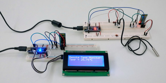
Пример 2: Удалённый мониторинг температуры
Этот пример немного сложнее. В отличие от примера 1, где ведущее устройство начинает отправлять данные сразу при запуске, здесь оно запрашивает данные у ведомого. Ведомое устройство получает запрос от ведущего и отвечает.
Ведомое устройство ждёт запроса sendTemp, затем считывает значение датчика температуры на пине A0, преобразует значение в градусы Цельсия и отправляет его в ASCII через программный последовательный канал. Скетчи используют ту же функцию recvWithStartEndMarkers(), поэтому данные оборачиваются в маркеры < и >.
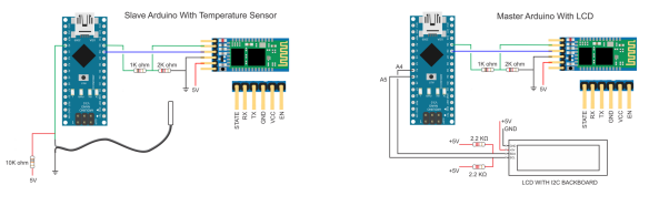
Как и прежде, Bluetooth-модули настроены на автоматическое подключение при запуске. Однако на этот раз используются 2 модуля HC-05: один в режиме Master, один в режиме Slave.
При запуске ведущее устройство инициализирует LCD и запускает таймер. Когда таймер срабатывает, отправляется запрос температуры. Таймер затем сбрасывается. В основном цикле скетч непрерывно проверяет полученные данные. При получении температуры она отображается на LCD.
Ведомое устройство просто ждёт запроса. При получении запроса отправляет температуру и возвращается к ожиданию.
Пример 2: Схема
Пример 2: Скетчи
Скетч на ведущем устройстве довольно прост. Раз в секунду он отправляет запрос ведомому устройству и ждёт ответ. Частоту запроса можно изменить, изменив значение waitTime. Нет проверки ошибок или тайм-аута, и скетч не знает, получил ли он когда-либо ответ.
/*
* Sketch: Arduino2Arduino_example2_RemoteTemp_Master
* By Martyn Currey
* 11.05.2016
* Written in Arduino IDE 1.6.3
*
* Send a temperature reading by Bluetooth
* Uses the following pins
*
* D8 - software serial RX
* D9 - software serial TX
* A0 - single wire temperature sensor
*
*
* AltSoftSerial uses D9 for TX and D8 for RX. While using AltSoftSerial D10 cannot be used for PWM.
* Remember to use a voltage divider on the Arduino TX pin / Bluetooth RX pin
* Download from https://www.pjrc.com/teensy/td_libs_AltSoftSerial.html
*/
#include <AltSoftSerial.h>
AltSoftSerial BTserial;


// If you don't have an LCD you can use the serial monitor.
// I use the LCD library from https://bitbucket.org/fmalpartida/new-liquidcrystal/wiki/Home
// if you use a different library change the following lines
#include <Wire.h>
#include <LiquidCrystal_I2C.h>
LiquidCrystal_I2C lcd(0x27, 2, 1, 0, 4, 5, 6, 7, 3, POSITIVE);  // Set the LCD I2C address


// define the pattern for a custom degree character. You can also use chr 233
byte degreeChr[8] = { B00111, B00101, B00111, B00000, B00000, B00000, B00000,};


// Set DEBUG to true to output debug information to the serial monitor
boolean DEBUG = true;


// Variables used for incoming data
const byte maxDataLength = 20;
char receivedChars[21] ;
boolean newData = false;

// Variables used for the timer
unsigned long startTime = 0;
unsigned long waitTime = 1000;

const byte TEMP_PIN = A0;


void setup()
{
  lcd.begin(20,4);
  lcd.createChar(1, degreeChr);
  lcd.setCursor(0,0);  lcd.print("Remote Temp Monitor");
  lcd.setCursor(0,1);  lcd.print("Starting...");

  if (DEBUG)
  {
       // open serial communication for debugging
       Serial.begin(9600);
       Serial.println(__FILE__);
       Serial.println(" ");
  }

    BTserial.begin(9600);
    if (DEBUG)  {  Serial.println("AltSoftSerial started at 9600");     }

    newData = false;
    startTime = millis();

} // void setup()


void loop()
{
    if (  millis()-startTime > waitTime )
    {
       BTserial.print("<sendTemp>");
       if (DEBUG) { Serial.println("Request sent"); }
       startTime = millis();
    }

    recvWithStartEndMarkers();
    if (newData)
    {
         if (DEBUG) { Serial.println("Data received"); }
         lcd.setCursor(0,1);   lcd.print("Temp = ");
         lcd.setCursor(7,1);   lcd.print(receivedChars);
         lcd.write(1);  lcd.print("C");
         newData = false;
         receivedChars[0]='\0';
    }
}


// function recvWithStartEndMarkers by Robin2 of the Arduino forums
// See  http://forum.arduino.cc/index.php?topic=288234.0
void recvWithStartEndMarkers()
{
     static boolean recvInProgress = false;
     static byte ndx = 0;
     char startMarker = '<';
     char endMarker = '>';
     char rc;

     if (BTserial.available() > 0)
     {
          rc = BTserial.read();
          if (recvInProgress == true)
          {
               if (rc != endMarker)
               {
                    receivedChars[ndx] = rc;
                    ndx++;
                    if (ndx > maxDataLength) { ndx = maxDataLength; }
               }
               else
               {
                     receivedChars[ndx] = '\0'; // terminate the string
                     recvInProgress = false;
                     ndx = 0;
                     newData = true;
               }
          }
          else if (rc == startMarker) { recvInProgress = true; }
     }
}
Скетч ведомого устройства столь же прост. Он ждёт запроса, и при получении отправляет текущую температуру.
/*
* Sketch: Arduino2Arduino_example2_RemoteTemp_Slave
* By Martyn Currey
* 11.05.2016
* Written in Arduino IDE 1.6.3
*
* Send a temperature reading by Bluetooth
* Uses the following pins
*
* D8 - software serial RX
* D9 - software serial TX
* A0 - single wire temperature sensor
*
*
* AltSoftSerial uses D9 for TX and D8 for RX. While using AltSoftSerial D10 cannot be used for PWM.
* Remember to use a voltage divider on the Arduino TX pin / Bluetooth RX pin
* Download from https://www.pjrc.com/teensy/td_libs_AltSoftSerial.html
*/
#include <AltSoftSerial.h>
AltSoftSerial BTserial;

// Set DEBUG to true to output debug information to the serial monitor
boolean DEBUG = true;


// Variables used for incoming data
const byte maxDataLength = 20;
char receivedChars[21] ;
boolean newData = false;

const byte TEMP_PIN = A0;


void setup()
{
    if (DEBUG)
    {
        // open serial communication for debugging
        Serial.begin(9600);
        Serial.println(__FILE__);
        Serial.println(" ");
    }

    //  open a software serial connection to the Bluetooth module.
    BTserial.begin(9600);
    if (DEBUG)  {   Serial.println(F("AltSoftSerial started at 9600"));     }
    newData = false;

} // void setup()


void loop()
{
    recvWithStartEndMarkers();
    if (newData)  {   processCommand();  }
}


/*
****************************************
* Function getTemp
* read an analogue pin and converts the value to a temperature
* based on the adafruit thermistor guide https://learn.adafruit.com/thermistor/testing-a-thermistor
*/
float getTemp()
{
    float reading = analogRead(TEMP_PIN);
    reading = 1023 / reading - 1;
    reading = 10000  / reading;
    float steinhart;
    steinhart = reading / 10000;          // (R/Ro)
    steinhart = log(steinhart);           // ln(R/Ro)
    steinhart /= 3950;                    // 1/B * ln(R/Ro)
    steinhart += 1.0 / (25 + 273.15);     // + (1/To)
    steinhart = 1.0 / steinhart;          // Invert
    steinhart -= 273.15;                  // convert to C
    return steinhart;

}


void processCommand()
{

     Serial.println(receivedChars);

     if (strcmp ("sendTemp",receivedChars) == 0)
     {
         float temp = getTemp();
         BTserial.print("<");  BTserial.print( temp ); BTserial.print(">");
         if (DEBUG) { Serial.print("Temp is ");   Serial.print(temp);  Serial.println("");   }
     }

     newData = false;
     receivedChars[0]='\0';

}


// function recvWithStartEndMarkers by Robin2 of the Arduino forums
// See  http://forum.arduino.cc/index.php?topic=288234.0
void recvWithStartEndMarkers()
{
     static boolean recvInProgress = false;
     static byte ndx = 0;
     char startMarker = '<';
     char endMarker = '>';
     char rc;

     if (BTserial.available() > 0)
     {
          rc = BTserial.read();
          if (recvInProgress == true)
          {
               if (rc != endMarker)
               {
                    receivedChars[ndx] = rc;
                    ndx++;
                    if (ndx > maxDataLength) { ndx = maxDataLength; }
               }
               else
               {
                     receivedChars[ndx] = '\0'; // terminate the string
                     recvInProgress = false;
                     ndx = 0;
                     newData = true;
               }
          }
          else if (rc == startMarker) { recvInProgress = true; }
     }

}