Основы работы с потенциометрами и Arduino
Узнайте об основах работы потенциометра, о формах, в которых он встречается, и о том, как использовать его в своих проектах.
Последнее обновление: 01/25/2022
Потенциометр — это простое механическое устройство, которое выпускается во множестве различных форм. Он обеспечивает переменное сопротивление, которое изменяется при манипуляциях с ним. В примерах этой статьи используется потенциометр с поворотным валом — одна из наиболее распространённых разновидностей потенциометров.
Подавая напряжение через потенциометр на аналоговый вход Arduino, можно измерить величину сопротивления потенциометра как аналоговое значение. В этой статье показаны варианты применения потенциометров, а также объясняется, как подключить их и считывать с них данные. В одном примере потенциометр используется как вход для смесителя цветов, в другом — показано, как точно выбирать цвета и плавно переходить между ними.
Типичный потенциометр имеет 3 вывода: два вывода питания (+5 В и GND) и один вывод, который подключается к аналоговому входному пину Arduino для считывания выходного значения.
Совет
Чтобы узнать, как считывать данные с потенциометра и отображать их в Мониторе последовательного порта, обратитесь к примеру Analog Read Serial.
Необходимое оборудование
Плата Arduino
Потенциометр
1 красный, 1 зелёный, 1 синий светодиод
3 резистора 220 Ом
Схема подключения
Вывод «+» потенциометра → 5V
Вывод «-» потенциометра → GND
Вывод данных потенциометра → A3
Красный светодиод подключён к выводу 9 через резистор 220 Ом
Зелёный светодиод подключён к выводу 10 через резистор 220 Ом
Синий светодиод подключён к выводу 11 через резистор 220 Ом
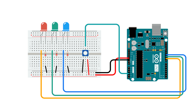
Полная схема подключения
Пример: смеситель цветов
Этот пример показывает, как потенциометр можно использовать в качестве аналогового входа для смешивания цветов с большой точностью.
/*
* Code for making one potentiometer control 3 LEDs, red, grn and blu, or one tri-color LED
* The program cross-fades from red to grn, grn to blu, and blu to red
* Clay Shirky <clay.shirky@nyu.edu>
*/

// INPUT: Potentiometer should be connected to 5V and GND
int potPin = A3; // Potentiometer output connected to analog pin 3
int potVal = 0; // Variable to store the input from the potentiometer

// OUTPUT: Use digital pins 9-11, the Pulse-width Modulation (PWM) pins
// LED's cathodes should be connected to digital GND
int redPin = 9;   // Red LED,   connected to digital pin 9
int grnPin = 10;  // Green LED, connected to digital pin 10
int bluPin = 11;  // Blue LED,  connected to digital pin 11

// Program variables
int redVal = 0;   // Variables to store the values to send to the pins
int grnVal = 0;
int bluVal = 0;

void setup()
{
  pinMode(redPin, OUTPUT);   // sets the pins as output
  pinMode(grnPin, OUTPUT);
  pinMode(bluPin, OUTPUT);
}

// Main program
void loop()
{
  potVal = analogRead(potPin);   // read the potentiometer value at the input pin

  if (potVal < 341)  // Lowest third of the potentiometer's range (0-340)
  {
    potVal = (potVal * 3) / 4; // Normalize to 0-255

    redVal = 256 - potVal;  // Red from full to off
    grnVal = potVal;        // Green from off to full
    bluVal = 1;             // Blue off
  }
  else if (potVal < 682) // Middle third of potentiometer's range (341-681)
  {
    potVal = ( (potVal-341) * 3) / 4; // Normalize to 0-255

    redVal = 1;            // Red off
    grnVal = 256 - potVal; // Green from full to off
    bluVal = potVal;       // Blue from off to full
  }
  else  // Upper third of potentiometer's range (682-1023)
  {
    potVal = ( (potVal-683) * 3) / 4; // Normalize to 0-255

    redVal = potVal;       // Red from off to full
    grnVal = 1;            // Green off
    bluVal = 256 - potVal; // Blue from full to off
  }
  analogWrite(redPin, redVal);   // Write values to LED pins
  analogWrite(grnPin, grnVal);
  analogWrite(bluPin, bluVal);
}
Пример: плавное перемещение цветов (crossfade)
/*
* Code for cross-fading 3 LEDs, red, green and blue (RGB)
* To create fades, you need to do two things:
*  1. Describe the colors you want to be displayed
*  2. List the order you want them to fade in
*
* DESCRIBING A COLOR:
* A color is just an array of three percentages, 0-100,
*  controlling the red, green and blue LEDs
*
* Red is the red LED at full, blue and green off
*   int red = { 100, 0, 0 }
* Dim white is all three LEDs at 30%
*   int dimWhite = {30, 30, 30}
* etc.
*
* Some common colors are provided below, or make your own
*
* LISTING THE ORDER:
* In the main part of the program, you need to list the order
*  you want to colors to appear in, e.g.
*  crossFade(red);
*  crossFade(green);
*  crossFade(blue);
*
* Those colors will appear in that order, fading out of
*    one color and into the next
*
* In addition, there are 5 optional settings you can adjust:
* 1. The initial color is set to black (so the first color fades in), but
*    you can set the initial color to be any other color
* 2. The internal loop runs for 1020 iterations; the 'wait' variable
*    sets the approximate duration of a single crossfade. In theory,
*    a 'wait' of 10 ms should make a crossFade of ~10 seconds. In
*    practice, the other functions the code is performing slow this
*    down to ~11 seconds on my board. YMMV.
* 3. If 'repeat' is set to 0, the program will loop indefinitely.
*    if it is set to a number, it will loop that number of times,
*    then stop on the last color in the sequence. (Set 'return' to 1,
*    and make the last color black if you want it to fade out at the end.)
* 4. There is an optional 'hold' variable, which pasues the
*    program for 'hold' milliseconds when a color is complete,
*    but before the next color starts.
* 5. Set the DEBUG flag to 1 if you want debugging output to be
*    sent to the serial monitor.
*
*    The internals of the program aren't complicated, but they
*    are a little fussy -- the inner workings are explained
*    below the main loop.
*
* April 2007, Clay Shirky <clay.shirky@nyu.edu>
*/

// Output
int redPin = 9;   // Red LED,   connected to digital pin 9
int grnPin = 10;  // Green LED, connected to digital pin 10
int bluPin = 11;  // Blue LED,  connected to digital pin 11

// Color arrays
int black[3]  = { 0, 0, 0 };
int white[3]  = { 100, 100, 100 };
int red[3]    = { 100, 0, 0 };
int green[3]  = { 0, 100, 0 };
int blue[3]   = { 0, 0, 100 };
int yellow[3] = { 40, 95, 0 };
int dimWhite[3] = { 30, 30, 30 };
// etc.

// Set initial color
int redVal = black[0];
int grnVal = black[1];
int bluVal = black[2];

int wait = 10;      // 10ms internal crossFade delay; increase for slower fades
int hold = 0;       // Optional hold when a color is complete, before the next crossFade
int DEBUG = 1;      // DEBUG counter; if set to 1, will write values back via serial
int loopCount = 60; // How often should DEBUG report?
int repeat = 3;     // How many times should we loop before stopping? (0 for no stop)
int j = 0;          // Loop counter for repeat

// Initialize color variables
int prevR = redVal;
int prevG = grnVal;
int prevB = bluVal;

// Set up the LED outputs
void setup()
{
  pinMode(redPin, OUTPUT);   // sets the pins as output
  pinMode(grnPin, OUTPUT);
  pinMode(bluPin, OUTPUT);

  if (DEBUG) {           // If we want to see values for debugging...
    Serial.begin(9600);  // ...set up the serial output
  }
}

// Main program: list the order of crossfades
void loop()
{
  crossFade(red);
  crossFade(green);
  crossFade(blue);
  crossFade(yellow);

  if (repeat) { // Do we loop a finite number of times?
    j += 1;
    if (j >= repeat) { // Are we there yet?
      exit(j);         // If so, stop.
    }
  }
}

/* BELOW THIS LINE IS THE MATH -- YOU SHOULDN'T NEED TO CHANGE THIS FOR THE BASICS
*
* The program works like this:
* Imagine a crossfade that moves the red LED from 0-10,
*   the green from 0-5, and the blue from 10 to 7, in
*   ten steps.
*   We'd want to count the 10 steps and increase or
*   decrease color values in evenly stepped increments.
*   Imagine a + indicates raising a value by 1, and a -
*   equals lowering it. Our 10 step fade would look like:
*
*   1 2 3 4 5 6 7 8 9 10
* R + + + + + + + + + +
* G   +   +   +   +   +
* B     -     -     -
*
* The red rises from 0 to 10 in ten steps, the green from
* 0-5 in 5 steps, and the blue falls from 10 to 7 in three steps.
*
* In the real program, the color percentages are converted to
* 0-255 values, and there are 1020 steps (255*4).
*
* To figure out how big a step there should be between one up- or
* down-tick of one of the LED values, we call calculateStep(),
* which calculates the absolute gap between the start and end values,
* and then divides that gap by 1020 to determine the size of the step
* between adjustments in the value.
*/

int calculateStep(int prevValue, int endValue) {
  int step = endValue - prevValue; // What's the overall gap?
  if (step) {                      // If its non-zero,
    step = 1020/step;              //   divide by 1020
  }
  return step;
}

/* The next function is calculateVal. When the loop value, i,
*  reaches the step size appropriate for one of the
*  colors, it increases or decreases the value of that color by 1.
*  (R, G, and B are each calculated separately.)
*/

int calculateVal(int step, int val, int i) {

  if ((step) && i % step == 0) { // If step is non-zero and its time to change a value,
    if (step > 0) {              //   increment the value if step is positive...
      val += 1;
    }
    else if (step < 0) {         //   ...or decrement it if step is negative
      val -= 1;
    }
  }
  // Defensive driving: make sure val stays in the range 0-255
  if (val > 255) {
    val = 255;
  }
  else if (val < 0) {
    val = 0;
  }
  return val;
}

/* crossFade() converts the percentage colors to a
*  0-255 range, then loops 1020 times, checking to see if
*  the value needs to be updated each time, then writing
*  the color values to the correct pins.
*/

void crossFade(int color[3]) {
  // Convert to 0-255
  int R = (color[0] * 255) / 100;
  int G = (color[1] * 255) / 100;
  int B = (color[2] * 255) / 100;

  int stepR = calculateStep(prevR, R);
  int stepG = calculateStep(prevG, G);
  int stepB = calculateStep(prevB, B);

  for (int i = 0; i <= 1020; i++) {
    redVal = calculateVal(stepR, redVal, i);
    grnVal = calculateVal(stepG, grnVal, i);
    bluVal = calculateVal(stepB, bluVal, i);

    analogWrite(redPin, redVal);   // Write current values to LED pins
    analogWrite(grnPin, grnVal);
    analogWrite(bluPin, bluVal);

    delay(wait); // Pause for 'wait' milliseconds before resuming the loop

    if (DEBUG) { // If we want serial output, print it at the
      if (i == 0 or i % loopCount == 0) { // beginning, and every loopCount times
        Serial.print("Loop/RGB: #");
        Serial.print(i);
        Serial.print(" | ");
        Serial.print(redVal);
        Serial.print(" / ");
        Serial.print(grnVal);
        Serial.print(" / ");
        Serial.println(bluVal);
      }
      DEBUG += 1;
    }
  }
  // Update current values for next loop
  prevR = redVal;
  prevG = grnVal;
  prevB = bluVal;
  delay(hold); // Pause for optional 'wait' milliseconds before resuming the loop
}